About CustomBlock Elements
Elements specify the entities of the CustomBlock that the associated activity affects.
You can add elements to a CustomBlock definition using the tools in the Block Editor.
Note: A CustomBlock definition must contain at least one element.
In CustomBlock definitions, elements specify points, distances, and angles that you want to modify in the Block reference.
When defining a CustomBlock element, you can specify:
- Special grip points to display on the Block geometry. Use the grip points to manipulate the Block reference outside the Block Editor. By default, grip points apear at the main points of the element.
- Labels to identify the properties defined by the element. The labels appear under Custom in the Properties palette where you can modify values or select options. Double-clicking an element label switches the label to editing mode.
You can use elements and activities in certain combinations only. These elements are available in the Block Editor and you can associate activities with them as follows:
| Element | Description | Available activities |
|---|---|---|
| Point | Defines the X and Y properties of the Block reference. | Move, Stretch |
| Linear | Defines the distance between two points in the CustomBlock definition. | Move, Stretch, Scale, Pattern |
| Polar | Defines the distance between two points and displays an angle value. | Move, Stretch, Scale, Pattern, Polar |
| XY | Defines the X and Y distance from the base point of the element. | Move, Stretch, Scale, Pattern |
| Rotation | Defines an angle for the CustomBlock reference. | Rotate |
| Alignment | Defines an alignment axis for the CustomBlock reference. | - |
| Mirror | Defines a mirror axis for the CustomBlock reference. | Mirror |
| Visibility | Defines visibility states. You can add only one visibility element to a CustomBlock definition. | - |
| Table | Defines a custom property that you can associate with a list of defined values for other elements. | Table activity |
| Basepoint | Defines one base point for the CustomBlock reference relative to the CustomBlock geometry | - |
 Use elements to specify the properties and grip points of the entity that you want to customize are visible and accessible outside the Block Editor.
Example:
Place a linear element on a wall to specify that you want to change the wall length during the insertion. To change the length of a linear entity, assign a Stretch activity to the Linear element.
Elements Representation
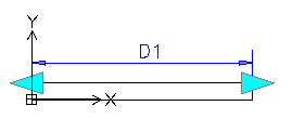
In the Block Editor, elements look very similar to Dimensions. The software automatically adds grip points that are associated with the main points of the elements.
Note: Only elements that have associated activities display grip points in the Block reference.
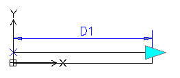
In the Block Editor, elements that do not have associated activities display this icon ![]() .
.
Double-clicking the warning icon ![]() displays the activities that you can associate to the element.
displays the activities that you can associate to the element.
Grip points available in the Block Editor:
| Grip Type | Icon | Modifications |
|---|---|---|
| Standard |  |
Moves, stretches, scales, or patterns entities independently in a Block reference. |
| Linear |  |
Lengthens, stretches, scales, or patterns entities in a Block reference in the direction specified by the element. |
| Rotation |  |
Rotates entities in a Block reference around an axis. |
| Alignment |  |
Aligns entities of a Block reference with other entities in the drawing, either tangentially or perpendicularly. |
| Flip |  |
Mirrors entities in a Block reference about an axis. |
| Table / Visibility |  |
Changes forms or dimensions based on predefined lists. Also, controls the visibility of subsets of entities based on lookup lists. |
Adding Grip Points to CustomBlocks Definitions
For any CustomBlock, you can create additional grip points to use to modify the geometry of Block references outside the Block Editor.
To specify additional grip points in a CustomBlock definition, add suitable elements on the entities you want to modify and specify the number of grip points you want to use. The grip point position in the CustomBlock definition is the grip point position in the Block reference.
You can specify the number of grip points at any time in the Properties palette (the Nr. of grips property).
Example:
A linear element for a wall has two grip points available by default. You can use both grip points or only one.
When you add an element to a CustomBlock definition, grip points appear at the main points of the element (points that you can use to manipulate the Block reference). Changing the grip point position does not affect the link with the main point. Moving the grip point in the Block reference affects the main point to which it is linked.
Make sure to correctly place the grip points in the CustomBlock definition to avoid potential confusion and unwanted results.
Example:
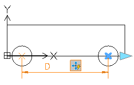
In the following example, a linear element defines a grip point. The move activity associates the grip point with the right circle and the end point of the element, which is the center of the circle.
Changing the grip point location in the CustomBlock definition does not affect the link with the main point (the center of the circle). In the Block reference, moving the grip point moves the right circle.
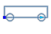
- Grip point at the main point position
Moving the grip point in the Block reference moves the circle.
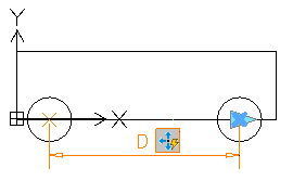
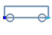
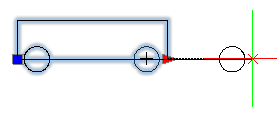
- Grip point in a different position
Moving the grip point in the Block reference moves the circle.
Specifying Insertion Cycling for Grip Points
Any grip point from the CustomBlock definition may become an insertion point in the Block reference. Use the CBCycleOrder command to specify the grip points that you can use as insertion points and their order in the list.
Pressing Ctrl key when inserting a CustomBlock with multiple insertion points lets you insert the Block from multiple position. However, the basepoint position does not change.
Specifying Value Sets for CustomBlocks
Use value sets to restrict an element to certain values when you insert a Block reference in a drawing.
You can specify a value set for these elements:
- Linear
- Polar
- Rotation
There are two methods to specify value sets:
- As a list of values
- As increments within a specified range.
Example:
In this example, you have a Custom Block defined to draw rectangular tables of various lengths. To limit the values, do one of the following:
- Specify a list of values for the length: 100, 120, 140 and 150 mm.
- Specify a range of values (from 100 .. 160) and an increment of 20. You can stretch the table to only 100, 120, 140, and 160mm.
To specify a value set for an element:
- Open the CustomBlock in the Block Editor.
- In the graphics area, specify the element.
- In the Properties palette, under Value Set, select an option:
- Increment. Specify the increment and the range of values:
- Increment. The difference between the values in the sequence.
- Initial value. First value in the sequence.
- End value. The last value in the sequence.
- List. Click
 to specify the list of values in the Value Set List dialog box.
- To add a specified value, click Add.
- To delete a value, select it from the list and click Delete.
- Increment. Specify the increment and the range of values: