Creating Drawings from the BIM Model
Use the BIMSection command to automatically create the following drawings from the BIM model:
- Plans
- Sections
- Elevations
Each drawing type has a specific graphical display and appears in a different branch in the BIM Navigator.
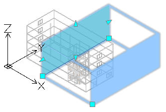
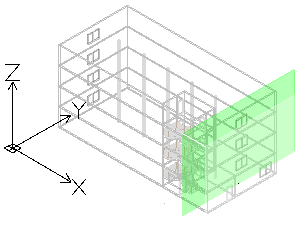
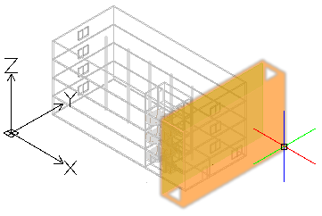
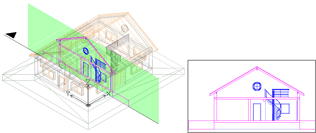
All drawing types are defined by a drawing volume clipping box which is specified by two points defining the drawing’s cutting plane, and a third point defining the drawing’s viewing direction and volume depth. BIM entities that are not within, or overlapping, the drawing volume clipping box are excluded from the drawing.
Note: Each drawing created from the same BIM model is stored in a separate .dwg file.
Plans
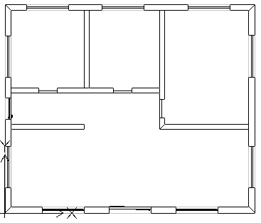
A plan drawing represents a horizontal slice through the BIM model. You can create floor plans.
You use a horizontal cutting plane to define a clipping box within the BIM model. Specify a depth to display entities of the BIM model below the cutting plane.
The BIM Navigator groups the plans in the Plans branch of the Drawings category in the BIM Navigator.
Sections
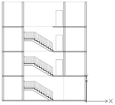
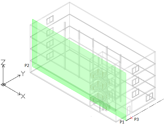
A section drawing represents a vertical slice through the BIM model.
The BIM Navigator groups the sections in the Sections branch.
Elevations
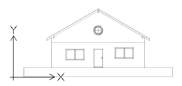
Elevation drawings represent a vertical view of a building. Unlike Sections, Elevation drawings do not slice through the building. Rather they represent views of the BIM from the outside from different directions. You can create north, south, east, and west elevation drawings.
The BIM Navigator groups the elevations in the Elevations branch of the drawings list in the Drawings category.
Working with the Clipping Box
The BIMSection command creates a clipping box with a specified width and depth. The first two points define the cutting plane position and the clipping box width, while the third point defines the drawing's view direction and depth into the viewing direction. The software calculates the height from the extents of the BIM geometry.
At any time, you can resize the clipping box to include a specific part of the BIM model or change the position of the cutting plane using grip points on the drawing clipping box.
Note: Refresh the corresponding drawing after modifying the size of the clipping box or the cutting plane position.
If you delete the clipping box, the corresponding BIM drawing is also deleted. Also, if you delete a BIM drawing, the corresponding clipping box is also deleted.
You can control the clipping box display.
To display the clipping box:
- In the BIM Navigator, in Drawings, select a drawing.
- At the bottom of the palette, select Show Clipping Box.
Hovering over the cutting plane (the green plane in the BIM Model) displays the entire clipping box.
Controlling the Representation of BIM Entities in Drawings
When you create a drawing based on a BIM model, the software automatically generates a set of specific layers on which the entities are placed according to their location within the drawings clipping box relative to the cutting plane. Each layer name includes the drawing name as layer name prefix, which lets you identify the layers of a drawing.
Each BIM drawing has a flatshot cut and a flatshot forward layer:
- Flatshot cut. Contains a flatshot representation of BIM entities that cross the drawings cutting plane.
- Flatshot forward. Contains BIM entities that are beyond the cutting plane, in forward direction.
You can use the Layers Manager to specify different representation of BIM entities depending on BIM entity location within the drawings clipping box relative to the cutting plane. Additionally, for any BIM entity from the drawing, the Properties palette lets you change the hatch.
Example:
| Flatshot cut |  |
| Flatshot forward |  |
To create a plan from a BIM model:
- In the graphics area, set up a suitable 2D view. Use the Views command.
For example, display the plan view of a floor.
- Do one of the following:
- On the ribbon, click BIM > Drawings > Plan.
- Type BIMSection and specify the Plan option.
- In the command window, specify the name of the plan and press Enter.
The plan appears in the BIM Navigator, in the Plans branch.
Note: Clicking Isolated
 to the right of the drawing in the drawing list in BIM Navigator displays the drawing in the graphics area. Clicking the button a second time hides the drawing and returns to the 3D model view.
To create a section from a BIM model:
 Before creating drawings, make sure you are working with the latest BIM model. Use the Reload from option to reload the latest BIM file from its location.
- In the graphics area, set up a suitable 3D view. Use the Views command.
- Do one of the following:
- On the ribbon, click BIM > Drawings > Section.
- Type BIMSection and specify the Section option.
A cutting plane is attached to the pointer.
Note: The cutting plane is perpendicular to the section line.
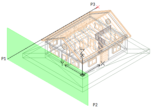
- In the graphics area, move the cutting plane preview to the desired location and click to specify the start point of the section line (P1).
- Specify the second point of the section line (P2).
- Specify a point or a value for the clipping box depth (P3).
- In the command window, specify the name of the section and press Enter.
The section appears in the BIM Navigator, in the Section branch.
Note: Clicking Isolated
to the right of the drawing in the drawing list in BIM Navigator displays the drawing in the graphics area. Clicking the button a second time hides the drawing and returns to the 3D model view.
To create an elevation from a BIM model:
- In the graphics area, set up a suitable 3D view. Use the Views command.
- Do one of the following:
- On the ribbon, click BIM > Drawings > Elevation.
- Type BIMSection and specify the Elevation option.
A cutting plane is attached to the pointer.
- In the graphics area, move the cutting plane preview to the desired location and click to specify the start point of the elevation line (P1).
- Specify the second point of the elevation line (P2).
- Specify a point or a value for the clipping box width (P3).
- In the command window, specify the name of the elevation and press Enter.
The elevation appears in the BIM Navigator, in the Elevation branch.
Access
Command: BIMSection
Ribbon: BIM > Drawings > Section
Related Topics
Parent Topic